<?xml version="1.0" encoding="utf-8"?><feed xmlns="http://www.w3.org/2005/Atom" ><generator uri="https://jekyllrb.com/" version="3.10.0">Jekyll</generator><link href="https://garyleecf.github.io/feed.xml" rel="self" type="application/atom+xml" /><link href="https://garyleecf.github.io/" rel="alternate" type="text/html" /><updated>2026-10-04T15:16:48+00:00</updated><id>https://garyleecf.github.io/feed.xml</id><title type="html">Gary C.F. Lee</title><subtitle>Academic website of Gary C.F. Lee, Research Scientist at A*STAR IAIC. Research in AI and learning-based methods for complex systems engineering, design, and architecture.</subtitle><author><name>Gary Lee</name><email>gary_lee@a-star.edu.sg</email></author><entry><title type="html">Connecting the Last Billion: The Engineering Challenges of Non-Terrestrial Networks</title><link href="https://garyleecf.github.io/6g/ubiquitous-connectivity-ntn/" rel="alternate" type="text/html" title="Connecting the Last Billion: The Engineering Challenges of Non-Terrestrial Networks" /><published>2026-07-12T00:00:00+00:00</published><updated>2026-07-12T00:00:00+00:00</updated><id>https://garyleecf.github.io/6g/ubiquitous-connectivity-ntn</id><content type="html" xml:base="https://garyleecf.github.io/6g/ubiquitous-connectivity-ntn/"><![CDATA[<p>This is the third and final post in the series on 6G’s three new scenarios. The <a href="/6g/uncovering-hidden-structures-in-wireless-systems-with-ai/">first</a> covered <em>AI and Communication</em>. The <a href="/6g/isac-sensing-communication/">second</a> covered <em>ISAC</em>. This one is about <strong>Ubiquitous Connectivity</strong>—and specifically, what it takes to extend cellular coverage to the places terrestrial networks will never reach.</p>

<hr />

<p>There is a version of the coverage problem that sounds almost solved. Cellular networks already cover most cities and suburbs. In developed countries, the uncovered population is a small fraction of the total. If you are reading this in an urban area, you have probably never thought much about coverage.</p>

<p>But “most” is not “all.” Large parts of the world—rural regions, oceans, disaster zones—have no terrestrial infrastructure and no realistic prospect of getting it. Building a cell tower that serves a hundred users in a remote region is not an economically viable proposition for any commercial operator. The terrestrial network closes the gap where density justifies deployment; but everywhere else, coverage ends.</p>

<p><strong>Ubiquitous Connectivity</strong>—one of 6G’s three new scenarios—is the proposal to close that remaining gap using non-terrestrial platforms: satellites in low Earth orbit (LEO), medium Earth orbit (MEO), and geostationary orbit (GEO), as well as high-altitude platform stations (HAPS) and aerial vehicles. The vision is a network where a handset in the middle of the Pacific Ocean, or on a cargo ship, or in a rural region with no tower in sight, can still reach the network.</p>

<p>The gap between vision and engineering reality is the interesting part.</p>

<hr />

<h2 id="two-very-different-approaches-to-the-same-goal">Two very different approaches to the same goal</h2>

<p>The phrase “satellite connectivity for phones” covers two architecturally distinct ideas, and conflating them causes a lot of confusion.</p>

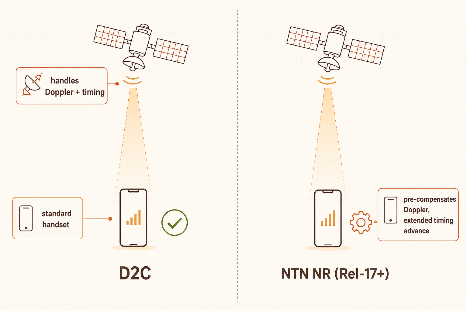
<p>The first is <strong>NTN Direct-to-Cell (D2C)</strong>. Here the satellite operates so that an ordinary, unmodified handset sees it as a regular base station. The phone does not know it is talking to something moving at 7 km/s in orbit. No software update, no new handset—the satellite handles the adaptation on its end. This is attractive commercially because the installed base of existing phones is enormous. The challenge is that doing this cleanly requires the satellite to compensate for all the complications—Doppler shift, propagation delay, timing advance—before the signal reaches the handset.</p>

<p>The second approach is <strong>NTN NR (3GPP NR for NTN)</strong>, standardized beginning with Release 17. Here the handset is NTN-aware. It knows it is talking to a satellite and participates in compensating for the challenges. It can pre-compensate for Doppler based on its own GNSS position, use extended timing advance for the longer round-trip delay, and handle other protocol-level adjustments. The phone needs to support these extensions, but the overall system design is cleaner because the work is shared.</p>

<p>The industry’s standardization momentum sits with <strong>3GPP Rel-17</strong>, which actually defines two NTN flavours: a more “IOT”-friendly, low-data-rate track (<strong>IoT-NTN</strong>, built on NB-IoT and eMTC) and the <strong>NTN NR</strong> track described above. The former is likely the first to roll out—its simpler protocol stack and existing infrastructure made it the earlier candidate, initially for low-rate messaging and IoT. NTN NR follows, with devices that implement the NTN-specific extensions becoming available over the next several years.</p>

<!-- IMAGE PROMPT for fig1-ntn-approaches.png | place file at /images/posts/ntn/fig1-ntn-approaches.png

Tech blog illustration in wide landscape format (3:2 ratio, 1536x1024 px). Dark navy background (#0D1B2A). Flat vector art with subtle neon glow effects. Accent colors: electric blue (#00B4D8), bright cyan (#06FFE8), amber (#FFB347).

Two side-by-side diagrams divided by a thin white vertical line. Both show a satellite icon at the top (small geometric satellite shape, electric blue) and a smartphone icon at the bottom.

Left panel (D2C): A clean downward signal beam from satellite to phone in bright cyan. The phone has a small green checkmark beside it suggesting "no changes needed". A label in bold white text centered below: "D2C". Small annotation boxes: satellite side shows "handles Doppler + timing", phone side shows "standard handset".

Right panel (NTN NR): Same satellite-to-phone beam in electric blue. The phone has a small amber gear/cog icon suggesting "NTN-aware". Annotation boxes: phone side shows "pre-compensates Doppler, extended timing advance". Label in bold white text: "NTN NR (Rel-17+)".

Faint dot-grid background. No other text. 1536x1024 landscape.
-->
<figure style="margin: 1.8em 0 1.4em;">
  <img src="/images/posts/ntn/fig1-ntn-approaches.png" alt="Two NTN approaches side by side: D2C where the satellite adapts so ordinary phones work unchanged, and NTN NR where the handset has protocol extensions for satellite operation" style="max-width: 100%;" />
  <figcaption style="text-align: center; font-size: 0.82em; margin-top: 0.5em;"><strong>Left:</strong> Direct-to-Cell---the satellite compensates for the channel; the handset needs no changes. <strong>Right:</strong> NTN NR---the handset participates in compensation via protocol extensions standardized in Release 17.</figcaption>
</figure>

<hr />

<h2 id="what-starlink-actually-isand-is-not">What Starlink actually is—and is not</h2>

<p>A clarification worth making explicitly: the Starlink most people are familiar with is not direct-to-cell connectivity. The original Starlink service requires a dedicated terminal—the flat phased-array dish colloquially known as Dishy—installed at a fixed or semi-fixed location. That terminal handles the satellite link and then provides Wi-Fi or Ethernet to devices nearby. A phone connected to Starlink via this route is effectively connecting to a local Wi-Fi access point, not to a satellite. The satellite link is backhaul.</p>

<p>This is a fundamentally different architecture from what “NTN for 5G/6G” implies. In the NTN vision, the phone’s cellular radio—the same radio it uses to call a terrestrial tower—connects directly to the satellite. No dish, no dedicated hardware on the ground, no special terminal.</p>

<p>SpaceX has announced direct-to-cell capability for newer Starlink satellites, and several carriers have signed partnership agreements. But this capability is distinct from the consumer Starlink service, uses different satellite hardware, and is still in early rollout. The earlier generation of Starlink constellation was not designed for it.</p>

<p>The distinction matters because the engineering problems are completely different. A large phased-array dish on the ground can handle the link budget, the pointing, and the protocol adaptation on behalf of the attached devices. A handset must do all of this within the power and antenna constraints of something designed to fit in a pocket.</p>

<hr />

<h2 id="why-putting-a-handset-on-a-satellite-link-is-hard">Why putting a handset on a satellite link is hard</h2>

<p>The engineering challenges of NTN are real and substantial. Each one is solvable in principle; the question is how much they cost in performance and complexity.</p>

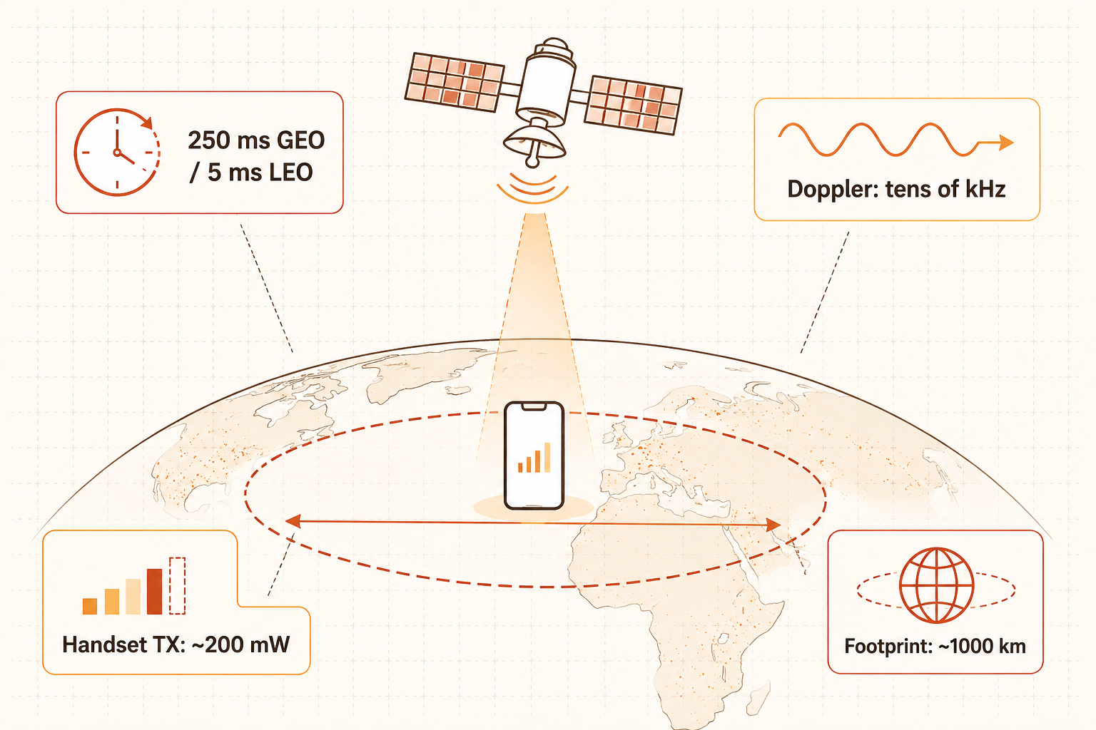
<p><strong>Distance and delay.</strong> A LEO satellite orbits at roughly 500 to 2,000 km altitude. Even at the low end, the one-way propagation delay is around 2 to 5 milliseconds—compared to microseconds for a nearby ground tower. Protocols designed for terrestrial cells assume very short round-trip times. NTN NR extends timing advance to handle this, but the delay has ripple effects throughout the protocol stack: random access preambles must be longer, HARQ retransmission timers need to accommodate the longer round-trip, and scheduling becomes harder to do at low latency. GEO satellites at 35,786 km have round-trip delays around 250 ms (one-way propagation alone is roughly 120 ms), which makes low-latency applications essentially infeasible from GEO—LEO is the only viable option for interactive use.</p>

<p><strong>Doppler shift.</strong> A LEO satellite moves at roughly 7 km/s relative to the ground. At cellular frequencies, this produces Doppler shifts that can be orders of magnitude larger than those seen in terrestrial channels. A terrestrial channel might see a few hundred Hz of Doppler from a fast-moving vehicle; a LEO satellite can produce shifts of tens of kHz. Standard receiver designs would misinterpret this as a frequency error. NTN NR asks the handset to pre-compensate based on its known position and the satellite’s ephemeris data—which works, but requires that the handset knows where it is (GNSS) and where the satellite is (ephemeris broadcast).</p>

<p><strong>Handset transmit power.</strong> A smartphone transmits at most around 23 to 26 dBm (roughly 200 to 400 mW). A base station can transmit at tens of watts. In a terrestrial cell, the uplink from handset to tower is often the limiting link—the tower hears the weak phone, not the other way around. Bridging an additional 500 km with a low-power handset is a link budget problem. The satellite needs large antennas and sensitive receivers to close the link; the handset has essentially no room to increase its transmit power.</p>

<p><strong>Cell size and capacity.</strong> A single LEO satellite at 600 km altitude with a reasonable beam pattern might illuminate a footprint several hundred kilometres in diameter. This is not like a terrestrial cell covering a neighbourhood—it is a cell covering a region the size of a small country. The number of users in that footprint can be very large. Massive MIMO and beam-forming on the satellite can subdivide the footprint into narrower spot beams, which is how most modern LEO NTN systems are designed. But each spot beam still covers tens of kilometres, not hundreds of metres, and the capacity implications are real.</p>

<p><strong>Handover.</strong> A LEO satellite moves across the sky in roughly 5 to 15 minutes from horizon to horizon. This means handover—from one satellite to the next, or from satellite to a terrestrial base station when one comes into range—happens frequently and must work reliably. Terrestrial handover has milliseconds to execute; NTN handover must be planned well in advance because the geometry is predictable.</p>

<!-- IMAGE PROMPT for fig2-ntn-challenges.png | place file at /images/posts/ntn/fig2-ntn-challenges.png

Tech blog illustration in wide landscape format (3:2 ratio, 1536x1024 px). Dark navy background (#0D1B2A). Flat vector art with subtle neon glow effects. Accent colors: electric blue (#00B4D8), bright cyan (#06FFE8), amber (#FFB347).

A single LEO satellite icon (small geometric satellite, electric blue) at the top center. Below it, a large gentle arc representing the Earth's surface (thin white curved line). A small smartphone icon sits on the surface below the satellite.

From the satellite, a downward signal beam in cyan. Around the scene, four small annotation clusters with bold white short labels and simple icons:

Top-left: a clock/timer icon + label "round-trip ~250 ms GEO / ~10 ms LEO" representing propagation delay.
Top-right: wavy arrow icon + label "Doppler: tens of kHz" representing Doppler shift.
Bottom-left: signal strength bar icon (low bars, amber) + label "Handset TX: ~200 mW" representing power constraint.
Bottom-right: large oval/ellipse on the Earth surface showing footprint + label "Footprint: ~1000 km" representing large cell size.

Clean, sparse layout. Faint dot-grid background. 1536x1024 landscape.
-->
<figure style="margin: 1.8em 0 1.4em;">
  <img src="/images/posts/ntn/fig2-ntn-challenges.png" alt="NTN engineering challenges illustrated: propagation delay, Doppler shift, handset transmit power limitation, and large satellite footprint" style="max-width: 100%;" />
  <figcaption style="text-align: center; font-size: 0.82em; margin-top: 0.5em;">Each challenge is a consequence of the geometry. Distance drives delay and link budget. Orbital velocity drives Doppler. Altitude drives footprint size. None of these are problems a terrestrial cell designer needed to solve.</figcaption>
</figure>

<hr />

<h2 id="frequency-matters-more-than-you-might-expect">Frequency matters more than you might expect</h2>

<p>The choice of frequency band has an outsized effect on what is and is not feasible for NTN.</p>

<p>Lower frequencies—L-band (1–2 GHz), S-band (2–4 GHz)—propagate well, penetrate buildings better, and require less transmit power to close the link at satellite distances. Iridium and Inmarsat, which have offered satellite connectivity to specialized terminals for decades, use L-band. The trade-off is that lower frequencies have less available bandwidth, which caps throughput.</p>

<p>Higher frequencies—Ku-band (12–18 GHz), which Starlink’s dish-based service uses for its user link, and Ka-band (26–40 GHz), which it uses for gateway links—offer much more bandwidth and support high throughput to large terminals. But for a handset, the link budget at these frequencies with a small antenna and limited transmit power simply does not close without heroic effort on the satellite side.</p>

<p>For NTN direct-to-cell, the industry is mostly looking at lower frequency bands: S-band and, in some cases, the existing cellular bands (especially the lower ones around 700–900 MHz). This is partly why LTE is first to roll out—LTE has always operated in these bands, and the protocol was designed for them. The frequency choice is not just a performance decision; it determines whether the link is physically possible with a standard handset at all.</p>

<hr />

<h2 id="the-industry-is-still-sorting-itself-out">The industry is still sorting itself out</h2>

<p>NTN is not a solved problem waiting for deployment. The standardization is relatively new—Rel-17 was completed in 2022, with device implementations still maturing. The commercial agreements between satellite operators and terrestrial carriers are being negotiated. The link budget analyses are being validated against real constellations. Several technical questions remain open: how to handle interference when satellite and terrestrial cells overlap in the same band, how to hand over reliably between satellite and ground, what service guarantees are actually achievable given the capacity constraints of a large footprint, and how to handle the regulatory patchwork of different frequency allocations across jurisdictions.</p>

<p>The space is also commercially crowded and fast-moving. AST SpaceMobile, which is targeting direct-to-cell with large-aperture satellites, is at a different stage of deployment than SpaceX’s Direct to Cell programme, which in turn is architecturally different from OneWeb’s or Amazon Kuiper’s approach. Each company has made different trade-offs between satellite size, frequency band, constellation altitude, and target use case. It is not yet clear which architecture will prove most tractable.</p>

<hr />

<h2 id="is-this-the-future">Is this the future?</h2>

<p>I honestly don’t know.</p>

<p>The coverage argument is real. There are parts of the world where terrestrial connectivity will not appear in any foreseeable commercial timeframe, and satellite NTN is probably the only credible path to connecting them. Maritime and aviation connectivity, which have historically required large specialized equipment, could be transformed by LEO NTN at reasonable cost. Emergency and disaster response use cases are compelling precisely because they need coverage when terrestrial infrastructure has failed.</p>

<p>But the capacity argument is harder. A satellite serving a footprint of hundreds of thousands of square kilometres is not going to replace a dense urban network. For high-traffic environments, the satellite can serve as a fallback—a safety net—not a primary access mechanism. Whether that is worth the complexity of integrating it into the 3GPP stack is a question the field is still working out.</p>

<p>What I am more confident about is that the engineering problems NTN is forcing the community to solve are hard and interesting. Handling large Doppler in a standard protocol stack, closing a link budget to a low-power handset from orbit, doing predictive handover across a fast-moving cell—these problems are accelerating innovation in areas that will benefit wireless systems more broadly, regardless of whether satellite connectivity becomes ubiquitous. In that sense, it is a bit like the moon landing: the goal may not be the point. The engineering dragged along in pursuit of it often is.</p>

<hr />

<p><em>This closes the three-part series on 6G’s new scenarios. Next, I will turn to some of the research directions that sit at the intersection of these themes—starting with how AI-native approaches are changing the way we think about channel estimation and resource management in practice.</em></p>

<hr />

<h3 id="references">References</h3>

<p>[1] ITU-R, “Framework and overall objectives of the future development of IMT for 2030 and beyond,” Recommendation ITU-R M.2160, International Telecommunication Union, Geneva, Nov. 2023. [Online]. Available: <a href="https://www.itu.int/rec/R-REC-M.2160/en">https://www.itu.int/rec/R-REC-M.2160/en</a></p>

<p>[2] 3GPP, “Solutions for NR to support non-terrestrial networks (NTN),” 3GPP TR 38.821 V16.0.0, Jan. 2020.</p>

<p>[3] O. Kodheli et al., “Satellite communications in the new space era: A survey and future challenges,” <em>IEEE Communications Surveys &amp; Tutorials</em>, vol. 23, no. 1, pp. 70–109, 2021.</p>

<p>[4] F. Rinaldi et al., “Non-terrestrial networks in 5G &amp; beyond: A survey,” <em>IEEE Access</em>, vol. 8, pp. 165178–165200, 2020.</p>]]></content><author><name>Gary Lee</name><email>gary_lee@a-star.edu.sg</email></author><category term="6G" /><category term="NTN" /><category term="Satellite" /><category term="Ubiquitous Connectivity" /><category term="6G" /><category term="LEO" /><summary type="html"><![CDATA[A satellite covering half a continent and a phone in your pocket were not designed for each other. Getting them to talk is a harder engineering problem than it might look---and the industry is still working out how.]]></summary></entry><entry><title type="html">Can a 6G Base Station Double as a Radar?</title><link href="https://garyleecf.github.io/6g/isac-sensing-communication/" rel="alternate" type="text/html" title="Can a 6G Base Station Double as a Radar?" /><published>2026-06-05T00:00:00+00:00</published><updated>2026-06-05T00:00:00+00:00</updated><id>https://garyleecf.github.io/6g/isac-sensing-communication</id><content type="html" xml:base="https://garyleecf.github.io/6g/isac-sensing-communication/"><![CDATA[<p>This is the second post in a three-part series on 6G’s new scenarios. The <a href="/6g/uncovering-hidden-structures-in-wireless-systems-with-ai/">first post</a> covered <em>AI and Communication</em>. This one is about <strong>Integrated Sensing and Communication (ISAC)</strong>.</p>

<hr />

<p>A radar and a base station look different from the outside. One is pointed at a certain region of interest (e.g., the sky scanning for aircraft or the sea scanning for vessels). The other is mounted on a rooftop, pointed at streets and buildings. But at the signal processing level, they are doing something surprisingly similar. And that similarity is the foundation of ISAC.</p>

<h2 id="what-a-radar-actually-does">What a radar actually does</h2>

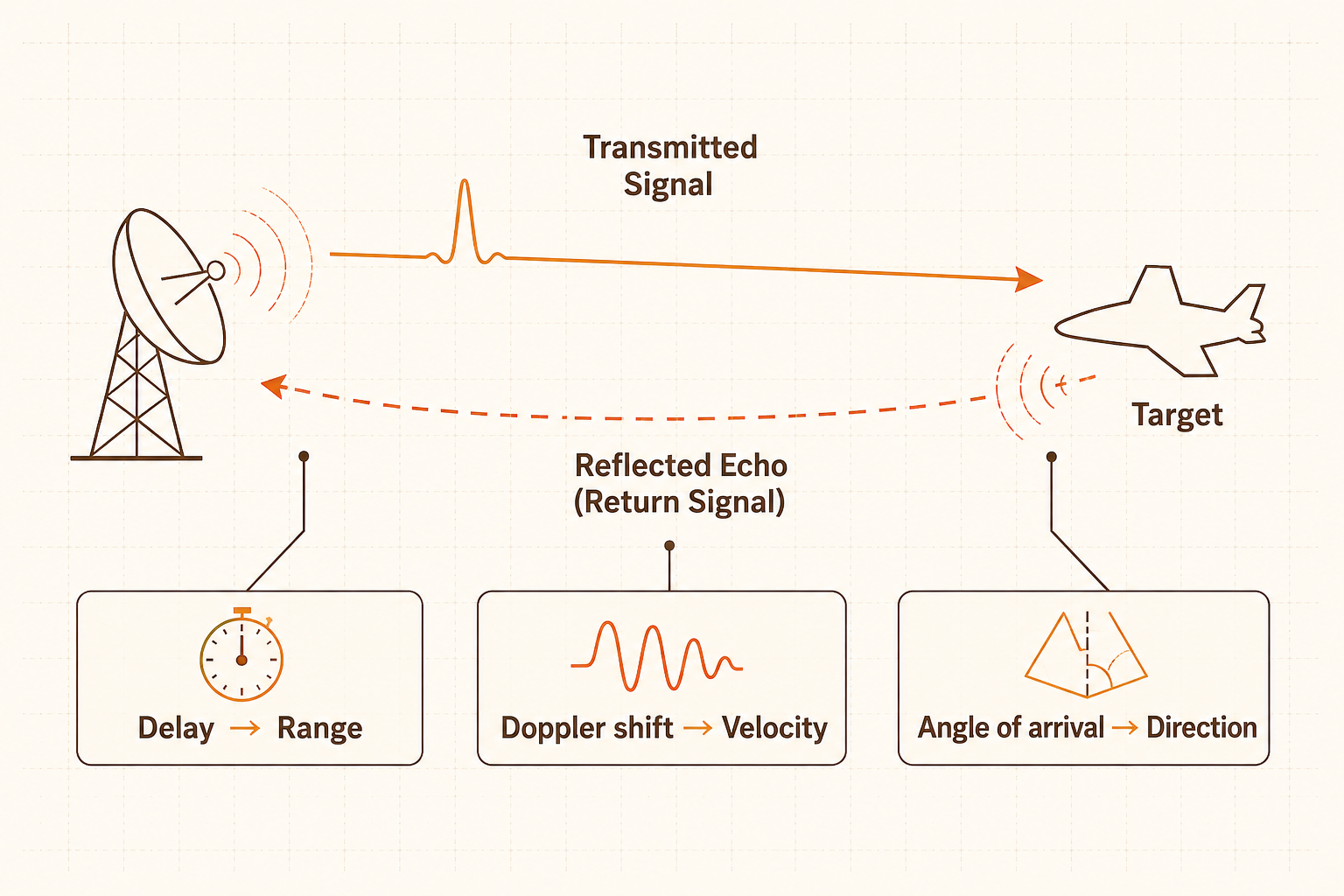
<p>A radar works on a simple principle: you transmit a signal (one you designed and know exactly), and that signal travels outward, hits an object, and some fraction of the energy reflects back. You receive the echo, compare it to what you originally sent, and from that comparison you can infer three things: how far away the object is (from the round-trip delay), how fast it is moving (from the Doppler frequency shift), and roughly what direction it came from (from the angle of arrival at your antenna array).</p>

<p>The key is that reference. Because you know what you transmitted, any deviation in the echo is signal, not noise. The delay tells you range. The frequency shift tells you velocity. The angle tells you direction. Radar is, at its core, <em>matched filtering</em> applied to a known waveform.</p>

<!-- IMAGE PROMPT for fig1-radar-principle.png | place file at /images/posts/isac/fig1-radar-principle.png

Tech blog illustration in wide landscape format (3:2 ratio, 1536x1024 px). Dark navy background (#0D1B2A). Flat vector art with subtle neon glow effects. Accent colors: electric blue (#00B4D8), bright cyan (#06FFE8), amber (#FFB347).

Horizontal diagram showing radar operation. Left side: a radar dish or antenna icon in electric blue. A transmitted signal pulse (glowing electric blue arrow) travels to the right toward a simple geometric target (small car or aircraft silhouette in white outline at center). A reflected echo signal (glowing cyan dashed arrow) curves back from the target toward the radar on the left. Below the diagram: three small annotation boxes in dark slate with white bold text: "Delay -> Range", "Doppler shift -> Velocity", "Angle of arrival -> Direction". The annotation boxes are connected by thin white lines to corresponding parts of the echo path. Faint dot-grid background. 1536x1024 landscape.
-->
<figure style="margin: 1.8em 0 1.4em;">
  <img src="/images/posts/isac/fig1-radar-principle.png" alt="Diagram of radar operation: a transmitted signal bounces off a target and the echo encodes range, velocity, and direction" style="max-width: 100%;" />
  <figcaption style="text-align: center; font-size: 0.82em; margin-top: 0.5em;">Radar extracts environmental information---range, velocity, direction---by comparing a known transmitted signal against its received echo.</figcaption>
</figure>

<h2 id="a-base-station-already-does-most-of-this">A base station already does most of this</h2>

<p>Now think about what a base station does during channel estimation. It transmits a known pilot signal, which is in effect a reference sequence both transmitter and receiver know in advance. The receiver measures what arrived and compares it to what was sent. From that comparison, it estimates how the channel distorted the signal: which paths exist, at what delays and angles, with what amplitudes.</p>

<p>That channel estimate is, implicitly, a description of the physical environment. The delay spread tells you something about the distances to the dominant scatterers. The angle of arrival tells you something about where objects are relative to the base station. The base station is already doing something structurally similar to radar; it is just using that information only for equalization, not for sensing.</p>

<p>The hardware prerequisites are largely similar. Wide bandwidth gives you range resolution: the finer the bandwidth, the shorter the delay differences you can distinguish, and therefore the more precise your range estimate. A massive MIMO antenna array gives you angular resolution: the more antennas, the narrower the spatial beams you can form, and the more precisely you can locate a scatterer. 5G base stations have both of these.</p>

<p>So why is ISAC a 6G feature rather than a 5G one? Partly standardization: sensing was not designed into the 5G specification. But more fundamentally, a 5G base station was not designed with sensing in mind. Its waveform, pilot structure, and resource allocation are all optimized for communication. Using it for sensing is possible, but you are working against some of its design choices rather than with them.</p>

<hr />

<h2 id="the-constraint-you-cannot-escape">The constraint you cannot escape</h2>

<p>A dedicated radar engineer has a freedom that a base station does not: the freedom to choose the waveform. Want better range resolution? Use a wider bandwidth chirp. Want to suppress range-Doppler ambiguity? Carefully design the pulse repetition interval. The waveform IS the radar’s primary design variable.</p>

<p>A base station must primarily transmit communications signal (conventionally, an OFDM waveform), because that is what its users expect. OFDM happens to work reasonably for sensing—the subcarrier structure gives you a natural time-frequency grid for delay-Doppler estimation, and you can extract channel information subcarrier by subcarrier. But “happens to work” is different from “designed for it.” Certain sensing tasks, like detecting slow-moving targets in high-clutter environments, for example, are hard with OFDM in ways they would not be with a purpose-built radar waveform.</p>

<p>The analogy is something like this: imagine someone who is an excellent musician asked to also take phone calls during a performance. They can do it. They may even handle both surprisingly well during quiet passages. But their attention is divided, and there will be moments where one task suffers for the other. A base station serving dense, high-traffic areas has limited spare capacity for sensing. A base station in a lightly loaded cell, with idle resource blocks and guard intervals, has much more headroom.</p>

<p>This is actually the intuition behind one of ISAC’s more defensible use cases: using the “quiet time” (unused slots, guard periods, idle bandwidth) for sensing at essentially zero comms cost. You are not competing with your primary job if there is no primary job happening at that moment.</p>

<!-- IMAGE PROMPT for fig2-isac-base-station.png | place file at /images/posts/isac/fig2-isac-base-station.png

Tech blog illustration in wide landscape format (3:2 ratio, 1536x1024 px). Dark navy background (#0D1B2A). Flat vector art with subtle neon glow effects. Accent colors: electric blue (#00B4D8), bright cyan (#06FFE8), amber (#FFB347).

Center: a base station tower icon with a massive MIMO antenna array, glowing electric blue. From the base station, two types of signals radiate simultaneously: narrow electric blue directional beam wedges pointing downward-left and downward-right toward two small smartphone user icons (communications beams). Separately, a wider cyan sensing beam points upward-right toward a small car icon driving along a road silhouette, with a dashed echo line returning from the car back to the base station (sensing echo in amber). A subtle split-focus visual effect on the base station---perhaps a faint dividing line or dual glow---suggests the station is doing two things at once. Faint dot-grid background. 1536x1024 landscape.
-->
<figure style="margin: 1.8em 0 1.4em;">
  <img src="/images/posts/isac/fig2-isac-base-station.png" alt="A base station simultaneously serving communication users with directional beams while sensing a moving vehicle with a separate sensing beam and receiving its echo" style="max-width: 100%;" />
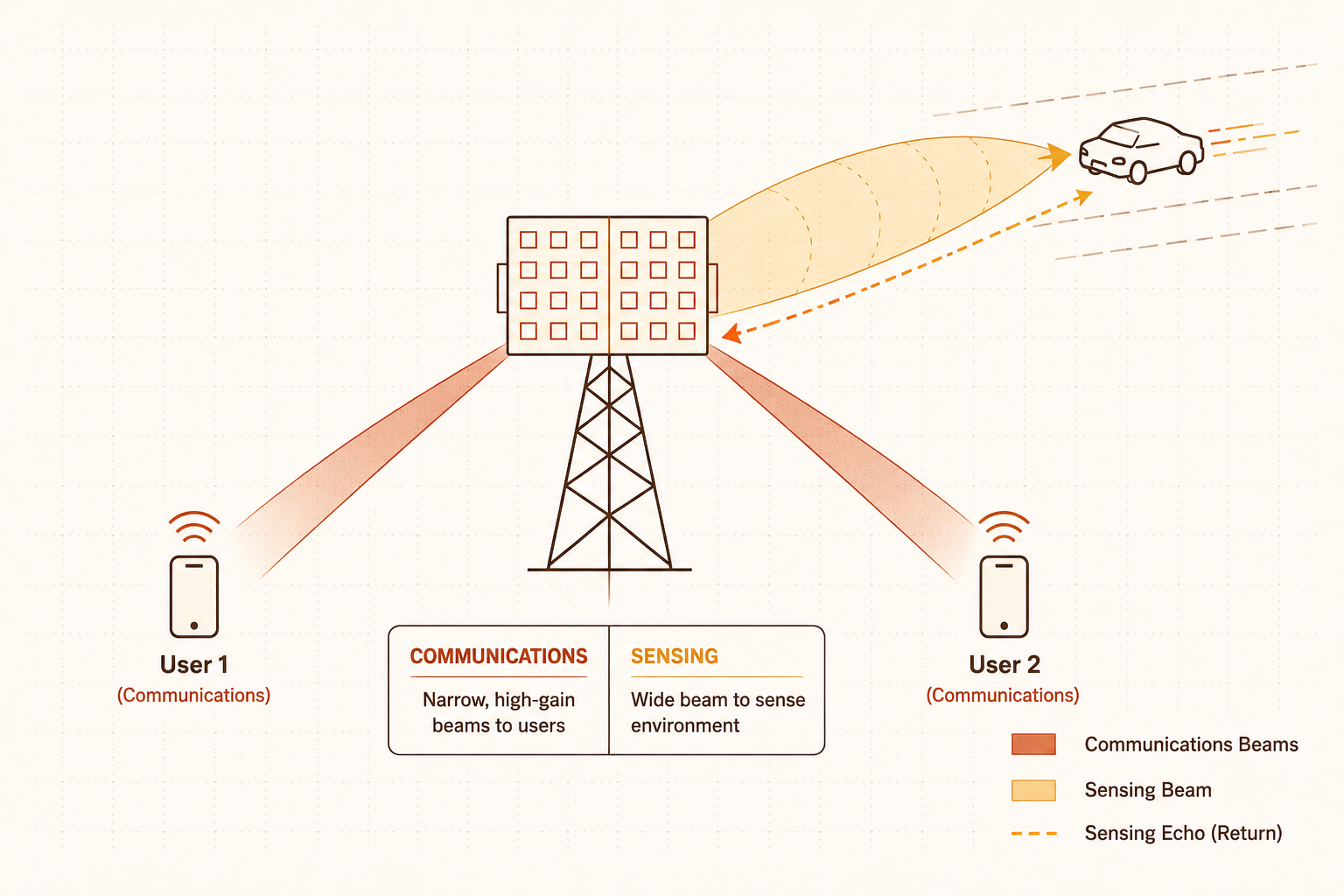
  <figcaption style="text-align: center; font-size: 0.82em; margin-top: 0.5em;">An ISAC base station allocates some of its resources to serving users (communications) and some to illuminating and receiving echoes from the environment (sensing). The challenge is that those resources are shared.</figcaption>
</figure>

<hr />

<h2 id="where-the-value-actually-is">Where the value actually is</h2>

<p>If a dedicated radar is better at sensing (which it generally is) why build ISAC at all? There are two arguments that hold up under scrutiny.</p>

<p><strong>The infrastructure argument.</strong> A radar network with the density of a cellular network would be staggering to deploy. Every city block, every indoor space, every industrial floor. To cover them with dedicated sensing hardware, the economics do not work for most applications. A 6G network, by contrast, will be deployed for communications reasons regardless. If each base station also senses, you get ubiquitous environmental awareness as a consequence of infrastructure that was going to exist anyway. The sensing might be lower quality than a dedicated radar, but its coverage is city-scale by default. That trade-off is worth taking seriously.</p>

<p><strong>The synergy argument.</strong> A standalone radar produces data—tracks of objects, maps of the environment—that then has to be transmitted to, processed by, and acted upon by some other system. In a cellular network, the sensing output can feed directly back into the communications system that generated it. Know where users are? Predict their beam before they move. Know there is a truck blocking a propagation path? Anticipate the shadow fading and adapt the link. The environment map is not a separate product delivered to a separate customer—it is an input to the comms system’s own operations. This closed-loop synergy has no analogue in standalone radar.</p>

<p>Taken together, these two arguments describe a scenario where ISAC is compelling not because it is a great radar, but because it is a good-enough sensor at a scale and integration depth that no dedicated sensor network can match.</p>

<hr />

<h2 id="but-be-careful-about-the-hype">But be careful about the hype</h2>

<p>Compared to a purpose-built radar system, an ISAC system will generally have worse sensing performance for a given hardware budget. The waveform is constrained. The antenna geometry is chosen for communications coverage, not radar cross-section optimization. Interference between the sensing and communications functions, particularly in multi-cell environments, is a real and open problem.</p>

<p>There is also a more subtle issue. Some of the most cited ISAC use cases (high-accuracy localization, gesture recognition, indoor mapping) require sensing quality that an ISAC system may not reliably deliver, especially in loaded networks where comms traffic leaves little room for sensing. The cases where ISAC clearly wins are the ones where moderate sensing quality, deployed everywhere, beats excellent sensing quality deployed somewhere. Not every application fits that description.</p>

<hr />

<h2 id="the-engineering-goes-deeper-than-one-post-can-cover">The engineering goes deeper than one post can cover</h2>

<p>This post has only sketched the shape of the argument. The actual engineering of an ISAC system—how you design waveforms that trade off comms and sensing performance, how you allocate resources between the two functions, how multiple ISAC nodes cooperate to form a distributed sensor array, what the fundamental limits look like—is a deep research area. So is the question of when ISAC’s value proposition holds up under rigorous system-level analysis, and when a hybrid deployment of simpler dedicated sensors alongside the base station would just be more practical.</p>

<p>A proper treatment of ISAC’s strengths, weaknesses, open research directions, and realistic deployment scenarios deserves its own post—one that goes further into the technical mechanics rather than staying at the conceptual level.</p>

<p>For now, the short version: ISAC is one of 6G’s most interesting bets. The hardware prerequisites are largely there. The value proposition for ubiquitous infrastructure sensing and comms-sensing synergy is real. But it will need honest benchmarking against alternatives—not just against other ISAC designs, but against the question of whether a standalone sensor network, or a hybrid approach, would serve the use case better.</p>

<hr />

<p><em>Next in the series: <strong>Ubiquitous Connectivity</strong>—what it means for 6G to extend coverage beyond where cell towers are economical to build, and why satellites and aerial platforms are part of that answer.</em></p>

<hr />

<h3 id="references">References</h3>

<p>[1] ITU-R, “Framework and overall objectives of the future development of IMT for 2030 and beyond,” Recommendation ITU-R M.2160, International Telecommunication Union, Geneva, Nov. 2023. [Online]. Available: <a href="https://www.itu.int/rec/R-REC-M.2160/en">https://www.itu.int/rec/R-REC-M.2160/en</a></p>

<p>[2] F. Liu, C. Masouros, A. P. Petropulu, H. Griffiths, and L. Hanzo, “Joint radar and communication design: Applications, state-of-the-art, and the road ahead,” <em>IEEE Transactions on Communications</em>, vol. 68, no. 6, pp. 3834–3862, Jun. 2020.</p>

<p>[3] C. Sturm and W. Wiesbeck, “Waveform design and signal processing aspects for fusion of wireless communications and radar sensing,” <em>Proceedings of the IEEE</em>, vol. 99, no. 7, pp. 1236–1259, Jul. 2011.</p>

<p>[4] A. Liu et al., “A survey on fundamental limits of integrated sensing and communication,” <em>IEEE Communications Surveys &amp; Tutorials</em>, vol. 24, no. 2, pp. 994–1034, 2022.</p>]]></content><author><name>Gary Lee</name><email>gary_lee@a-star.edu.sg</email></author><category term="6G" /><category term="ISAC" /><category term="Sensing" /><category term="Radar" /><summary type="html"><![CDATA[A 6G base station and a radar have more in common than it might seem. ISAC---Integrated Sensing and Communication---is the 6G scenario that takes that similarity seriously. Here is where the value proposition holds up, and where it deserves a harder look.]]></summary></entry><entry><title type="html">Uncovering Hidden Structures in Wireless Systems with AI</title><link href="https://garyleecf.github.io/6g/uncovering-hidden-structures-in-wireless-systems-with-ai/" rel="alternate" type="text/html" title="Uncovering Hidden Structures in Wireless Systems with AI" /><published>2026-04-08T00:00:00+00:00</published><updated>2026-04-08T00:00:00+00:00</updated><id>https://garyleecf.github.io/6g/uncovering-hidden-structures-in-wireless-systems-with-ai</id><content type="html" xml:base="https://garyleecf.github.io/6g/uncovering-hidden-structures-in-wireless-systems-with-ai/"><![CDATA[<p>Last post, I described the six usage scenarios that define 6G—the three evolved service classes from 5G, and three new ones: <strong>Integrated Sensing and Communication (ISAC)</strong>, <strong>AI and Communication</strong>, and <strong>Ubiquitous Connectivity</strong>. This post is the first of three going deeper on each. I am starting with <em>AI and Communication</em>, partly because it sits closest to my own research, and partly because it is the scenario that most directly challenges how wireless systems have been built for the last several decades.</p>

<p>The ITU’s framing—<em>AI and Communication</em>, not “AI for communication”—is intentional (I believe). The proposition is not that AI will enhance a communication network from the outside. It is that AI becomes part of the design fabric of the network itself (so-called “AI-native”). What does that actually mean in practice?</p>

<p>The short version: some of the assumptions that wireless systems were built on are worth revisiting. They are not wrong exactly, but are perhaps simplifications that kept the mathematics and analysis tractable, and they served the field well. However, at higher frequencies, where a significant share of 5G’s and 6G’s performance ambitions live, those simplifications start to cost something real and measurable. AI-native design is, in part, a proposal to stop leaving that performance on the table.</p>

<hr />

<h2 id="simplification-in-our-comfort-zone">Simplification in our comfort zone</h2>

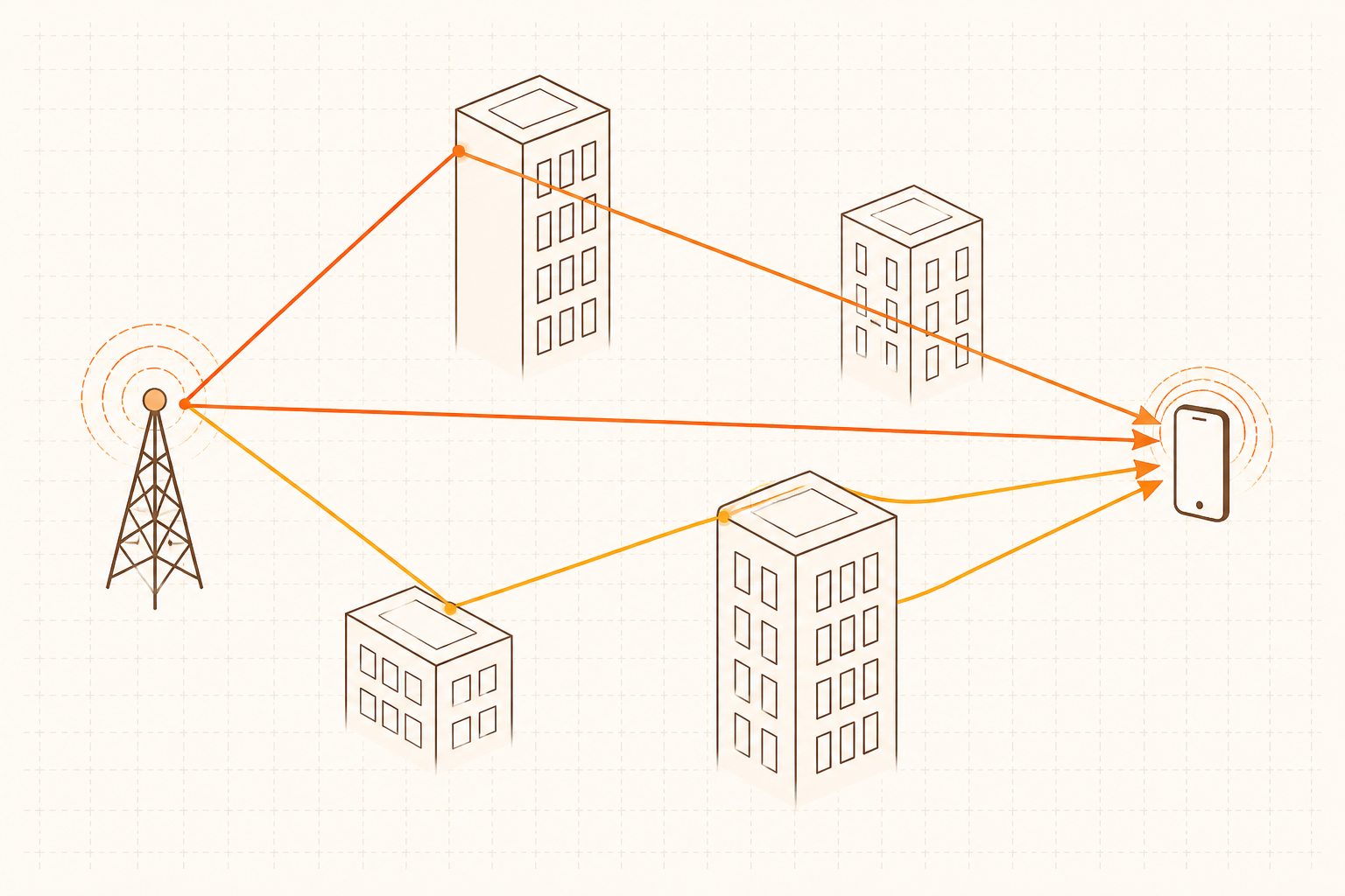
<p>When a signal traverse through the air, it doesn’t go point to point in a single straight line. It scatters, bounces off buildings, diffracts around corners, reflects off vehicles, gets absorbed by foliage. By the time it arrives at the receiver, it comprises dozens of paths, each at a slightly different angle, different delay, and different amplitude.</p>

<!-- IMAGE PROMPT for fig1-multipath.png | place file at /images/posts/ai-native-6g/fig1-multipath.png

Tech blog illustration in wide landscape format (3:2 ratio, 1536x1024 px). Dark navy background (#0D1B2A). Flat vector art with subtle neon glow effects. Accent colors: electric blue (#00B4D8), bright cyan (#06FFE8).

A wireless transmitter (small antenna tower icon, electric blue glow, left side) and a receiver (small smartphone icon, cyan glow, right side). Between them, multiple signal paths: one straight direct line-of-sight path in bright electric blue. Two or three reflected paths in cyan that curve and bounce off simple rectangular building silhouettes (thin white-line outlines, dark filled). One path visibly diffracts around a building corner as a gentle arc. Each path is a glowing arrow-tipped line. The paths arrive at the receiver from slightly different angles, suggesting the multipath effect. Faint dot-grid overlay on background. No text. 1536x1024 landscape.
-->
<figure style="margin: 1.8em 0 1.4em;">
  <img src="/images/posts/ai-native-6g/fig1-multipath.png" alt="Diagram showing a wireless signal traveling from transmitter to receiver via multiple scattered paths, representing multipath propagation" style="max-width: 100%;" />
  <figcaption style="text-align: center; font-size: 0.82em; margin-top: 0.5em;">A signal traveling through a real environment does not take a single path. Scattering, reflection, and diffraction produce a superposition of many arrivals at the receiver.</figcaption>
</figure>

<p>Characterising that precisely is, in general, very hard. So classical theory made a practical decision: if you have many independent random contributions summing together, invoke the central limit theorem, and the aggregate looks Gaussian, i.e., white noise, Rayleigh fading. A handful of parameters with tractable models.</p>

<p>This is an impressive line of reasoning, and it has been extraordinarily productive. Shannon capacity, optimal receiver design, error-correcting codes—most of what we actually deploy runs on Gaussian foundations.</p>

<p>But it is still an approximation. And as we push into higher frequencies like millimetre-wave and upper mid-bands (in line with 6G’s ambition for high throughputs), that approximation starts to cost us something real.</p>

<hr />

<h2 id="the-channel-that-gets-simpler-and-stranger-at-the-same-time">The channel that gets simpler and stranger at the same time</h2>

<p>Here is something that might surprise people when they first encounter it. You might expect that going to higher frequencies makes the wireless channel more chaotic. More reflections, more unpredictability. In fact, it goes the other way.</p>

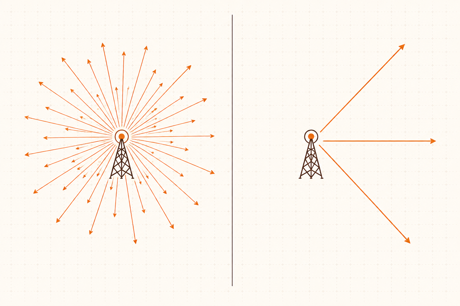
<p>At higher frequencies (millimetre-wave for instance), signals attenuate aggressively. Most of those scattered bounces just disappear. What you are left with is a small number of dominant propagation paths: a line-of-sight component if you are lucky, a strong reflection off a nearby surface, and then basically nothing else (at least not discernible from the background noise). The channel is <em>sparse</em> in the angular domain. Energy arrives from a few directions, not all of them.</p>

<!-- IMAGE PROMPT for fig2-sparse-channel.png | place file at /images/posts/ai-native-6g/fig2-sparse-channel.png

Tech blog illustration in wide landscape format (3:2 ratio, 1536x1024 px). Dark navy background (#0D1B2A). Flat vector art with subtle neon glow effects. Accent colors: electric blue (#00B4D8), bright cyan (#06FFE8).

Two side-by-side top-down diagrams of a base station radiating signals, divided by a thin white vertical line. Left panel: many thin overlapping signal rays (15 to 20) radiating outward in nearly all directions from a central antenna icon, in muted cyan of roughly equal intensity---represents rich multipath at sub-6GHz. Right panel: only 2 to 3 prominent sharp directional beams radiating from the same antenna icon in bright electric blue with a glow effect; the majority of directions are empty and dark---represents a sparse mmWave channel. Faint dot-grid background. No text. 1536x1024 landscape.
-->
<figure style="margin: 1.8em 0 1.4em;">
  <img src="/images/posts/ai-native-6g/fig2-sparse-channel.png" alt="Comparison of sub-6GHz rich multipath (many signal rays in all directions) versus mmWave sparse channel (2-3 dominant directional beams)" style="max-width: 100%;" />
  <figcaption style="text-align: center; font-size: 0.82em; margin-top: 0.5em;">At sub-6GHz frequencies, energy arrives from many directions simultaneously (left). At millimetre-wave, higher path loss strips away most reflections, leaving only a handful of dominant propagation paths (right).</figcaption>
</figure>

<p>This is not a messier channel. It is, in a meaningful sense, a more structured one.</p>

<p>The problem is that a Gaussian model does not know this. It has no prior that says energy should be concentrated in any particular direction. It treats all angles equally. It is like trying to find a face in a photograph by averaging over every possible configuration of pixels—technically defensible, practically wasteful.</p>

<p>The performance cost shows up most clearly in how the network designs its <em>codebook</em>, i.e., the set of beams it uses to serve users across a cell.</p>

<hr />

<h2 id="a-concrete-example-the-codebook-problem">A concrete example: the codebook problem</h2>

<p>In a massive MIMO system, the base station does not broadcast in all directions at once. It forms focused beams and allocates them to users. The collection of beams it can choose from is the codebook.</p>

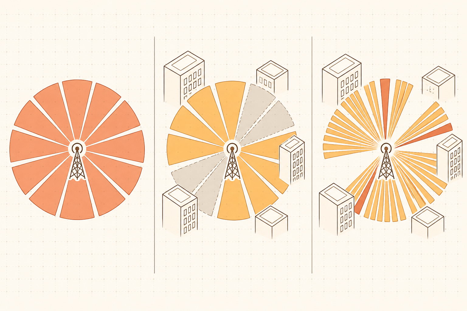
<p>The uninformed approach is to spread those beams uniformly across all possible angles. If a user could be <em>anywhere</em>, cover everything equally. That is fig. 3a: several beams, evenly spaced, no assumptions made about the world.</p>

<p>Now add the environment. Users are in buildings, on streets, in corridors. The geometry constrains where they actually are. Some angular directions from any given base station are simply not accessible—blocked by a wall, a building, a car park. That is fig. 3b. The codebook has not changed, but now it is obvious that some beams are pointing at regions where no user will ever be. Those are wasted degrees of freedom, since they are capacity you provisioned for but cannot use.</p>

<p>Fig. 3c is where it gets interesting. Same number of beams, but now shaped around where users can actually be. The inaccessible zones get nothing. The accessible ones get finer angular resolution, tighter beams, better spatial separation between users. The codebook has not grown; it has been <em>informed</em>.</p>

<!-- IMAGE PROMPT for fig3-codebook.png | place file at /images/posts/ai-native-6g/fig3-codebook.png

Tech blog illustration in wide landscape format (3:2 ratio, 1536x1024 px). Dark navy background (#0D1B2A). Flat vector art with subtle neon glow effects. Accent colors: electric blue (#00B4D8), bright cyan (#06FFE8), amber (#FFB347).

Three side-by-side top-down diagrams (3a, 3b, 3c), each showing a small base station icon at center with beam sectors radiating outward. Thin white vertical lines separate the three panels.

Panel 3a (left): 12 uniform triangular beam sectors evenly distributed 360 degrees around the base station, all equal-width electric blue wedges---uniform codebook, no assumptions.

Panel 3b (center): Same 12 beams as 3a. Three or four sectors are filled with a dark opaque overlay representing inaccessible zones blocked by solid dark rectangular building silhouettes around the perimeter. The blocked beam sectors are muted and dark; the accessible sectors are in cyan.

Panel 3c (right): Beams redistributed. The inaccessible zones receive no beams. The accessible zones receive more beams with narrower, finer angular resolution wedges packed closely, in bright cyan with a glow, and amber highlights on the most prominent beams---an informed codebook shaped by real geometry.

No text. 1536x1024 landscape.
-->
<figure style="margin: 1.8em 0 1.4em;">
  <img src="/images/posts/ai-native-6g/fig3-codebook.png" alt="Three top-down beam codebook diagrams: (a) uniform beams in all directions, (b) same beams with inaccessible zones shown, (c) beams redistributed and concentrated in accessible directions" style="max-width: 100%;" />
  <figcaption style="text-align: center; font-size: 0.82em; margin-top: 0.5em;"><strong>Left:</strong> A uniform codebook makes no assumptions about the environment. <strong>Center:</strong> In practice, a portion of those beams point into regions no user can reach. <strong>Right:</strong> An informed codebook concentrates angular resolution where it is actually needed.</figcaption>
</figure>

<p>The performance difference between a uniform and an informed codebook is not small. In dense urban deployments, it translates directly into how many users a cell can serve simultaneously—the kind of gain that shows up in system-level throughput, not just in link-level simulations [3]. The question is how you get the informed version. You could derive it analytically if you have a sufficiently accurate model of the environment. But real environments are messy, partial, and irregular—the clean analytical derivation gets complicated quickly. The increasingly practical answer is to learn it.</p>

<hr />

<h2 id="structure-you-can-learn-without-being-able-to-describe">Structure you can learn without being able to describe</h2>

<p>Learned estimators sidestep the commitment that compressed sensing requires, and this is where the argument connects back to the non-Gaussian point.</p>

<p>If you know the channel is sparse, you can exploit it directly. Compressed sensing algorithms (e.g., matching pursuit, LASSO) recover sparse signals from far fewer measurements than a Gaussian estimator would require. You don’t need to probe every direction if you know most directions are empty. This idea has been influential in 5G channel estimation research [2].</p>

<p>But compressed sensing requires you to specify the sparsity structure: which basis the channel is sparse in, how sparse, what the noise model looks like. Get those wrong and the gains disappear. Real millimetre-wave channels are sparse in ways that are approximately but not exactly what a textbook model says—the support varies with environment, there are correlations across antenna arrays that the standard basis ignores.</p>

<p>A learned estimator sidesteps this commitment. Train a neural network on empirical channel data from the actual deployment (the real buildings, the real mobility patterns, the real interference) and it absorbs the statistical structure of that environment without requiring you to write it down analytically. It learns that energy arrives from <em>these</em> angular ranges, in <em>these</em> cluster shapes. Not because you specified it. Because the data showed it.</p>

<p>The adapted codebook in fig. 3c is one illustration of the same principle. But the logic extends to channel estimation, CSI compression, beam management—anywhere the system currently makes a Gaussian assumption and pays a performance tax for it.</p>

<hr />

<h2 id="why-this-is-an-architecture-problem-not-just-an-algorithm-problem">Why this is an architecture problem, not just an algorithm problem</h2>

<p>Here is the part that often gets skipped over, and it matters.</p>

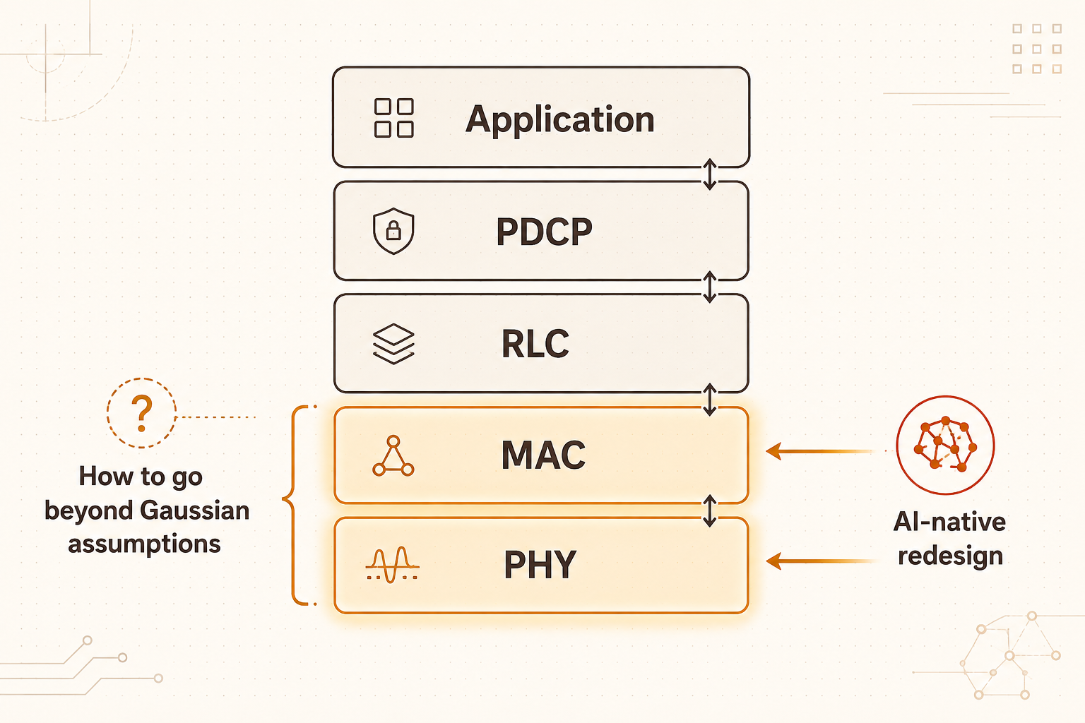
<p>The interface contracts between layers of the communications stack were designed around the Gaussian assumption—what the physical layer measures and reports, what the UE feeds back to the base station, what the channel model looks like to the scheduler. Pilot structures, feedback codebook formats, link adaptation curves: most of it was dimensioned for a particular model of what channels look like.</p>

<!-- IMAGE PROMPT for fig4-stack.png | place file at /images/posts/ai-native-6g/fig4-stack.png

Tech blog illustration in wide landscape format (3:2 ratio, 1536x1024 px). Dark navy background (#0D1B2A). Flat vector art with subtle neon glow effects. Accent colors: electric blue (#00B4D8), bright cyan (#06FFE8), amber (#FFB347).

Center of image: a vertical protocol stack---5 horizontal rounded-rectangle layers stacked from bottom to top. Each layer has a short bold white sans-serif label centered inside it. From bottom to top the labels read: "PHY", "MAC", "RLC", "PDCP", "Application". The bottom two layers (PHY and MAC) have a warm amber glow around their borders and a slightly brighter interior, indicating where classical Gaussian assumptions are embedded. The top three layers are in muted dark slate with minimal glow and their labels in lighter gray.

On the left side of the stack, a thin amber vertical bracket spans the PHY and MAC layers with a small bold white label beside it reading "How to go beyond Gaussian assumptions". On the right side, thin bright cyan arrows point inward toward the PHY and MAC layers with a glow effect, with a small bold white label reading "AI-native redesign". Thin white connecting arrows between adjacent layers on the right edge of the stack show internal interfaces.

Clean, symmetric, legible text. Faint dot-grid background. 1536x1024 landscape.
-->
<figure style="margin: 1.8em 0 1.4em;">
  <img src="/images/posts/ai-native-6g/fig4-stack.png" alt="Communications protocol stack diagram with the physical and MAC layers highlighted as the location of Gaussian assumptions, and AI-native redesign indicated at those layers" style="max-width: 100%;" />
  <figcaption style="text-align: center; font-size: 0.82em; margin-top: 0.5em;">The classical Gaussian assumption is baked into the lower layers of the stack---pilot structures, feedback formats, link adaptation curves. An AI-native system redesigns those interfaces, not just the algorithms running above them.</figcaption>
</figure>

<p>If you swap in a better estimator but leave those interfaces unchanged, you recover some performance. But you are still operating through specifications built for a different world. An AI-native system is one where those interface contracts are redesigned from the ground up around the assumption that learned representations will be doing the heavy lifting. Change the estimator <em>and</em> the contract, and the gains compound.</p>

<p>This is the architectural claim in IMT-2030’s <em>AI and Communication</em> scenario. The network is not getting a smarter add-on. It is being rethought from the physical layer up, around the premise that the old approximations were holding it back.</p>

<hr />

<h2 id="what-this-enables">What this enables</h2>

<p>The practical consequence is a network that adapts to its actual environment rather than a textbook approximation of it.</p>

<p>Conventional systems are designed to worst-case specifications—dimensioned for a channel that could be anywhere in the space the Gaussian model defines. A system that has learned the real distribution of channels in its deployment can afford to be more aggressive: finer codebooks, more targeted estimation, beam management tuned to local geometry. In dense urban millimetre-wave deployments, where the channel is sparse and structured, the gap between <em>designed-for-the-model</em> and <em>designed-for-the-reality</em> is large and exploitable.</p>

<p>The deeper point is about information. Real channels carry more structure than Gaussian models capture. A system built to learn and exploit that structure gets more performance from the same spectrum and hardware—not because it is more powerful, but because it has stopped making assumptions that were never quite true or overly pessimistic.</p>

<p>That is the AI-native proposition. Not AI as a layer on top of a classical system. AI as the thing that finally lets the network close the gap between the world it was designed for and the world it actually operates in.</p>

<hr />

<p><em>Next in the series: the other two new 6G scenarios—what it means for a network to also be a sensor (<strong>ISAC</strong>), and how 6G plans to extend coverage to places a cell tower was never economical to build (<strong>Ubiquitous Connectivity</strong>).</em></p>

<hr />

<h3 id="references">References</h3>

<p>[1] ITU-R, “Framework and overall objectives of the future development of IMT for 2030 and beyond,” Recommendation ITU-R M.2160, International Telecommunication Union, Geneva, Nov. 2023. [Online]. Available: <a href="https://www.itu.int/rec/R-REC-M.2160/en">https://www.itu.int/rec/R-REC-M.2160/en</a></p>

<p>[2] W. U. Bajwa, J. Haupt, A. M. Sayeed, and R. Nowak, “Compressed channel sensing: A new approach to estimating sparse multipath channels,” <em>Proceedings of the IEEE</em>, vol. 98, no. 6, pp. 1058–1076, Jun. 2010.</p>

<p>[3] A. Alkhateeb, O. El Ayach, G. Leus, and R. W. Heath, “Channel estimation and hybrid precoding for millimeter wave cellular systems,” <em>IEEE Journal of Selected Topics in Signal Processing</em>, vol. 8, no. 5, pp. 831–846, Oct. 2014.</p>]]></content><author><name>Gary Lee</name><email>gary_lee@a-star.edu.sg</email></author><category term="6G" /><category term="Machine Learning" /><category term="Data-Driven" /><category term="Wireless" /><category term="Channel Estimation" /><category term="AI-Native" /><summary type="html"><![CDATA[Wireless systems have been built on a Gaussian approximation for decades. At higher frequencies, that approximation starts to cost something real. AI-native 6G is, in part, a proposal to uncover and take advantage of the hidden structure.]]></summary></entry><entry><title type="html">What is the deal with 5G? Is it really faster?</title><link href="https://garyleecf.github.io/5g/what-is-wireless/" rel="alternate" type="text/html" title="What is the deal with 5G? Is it really faster?" /><published>2026-04-01T00:00:00+00:00</published><updated>2026-04-01T00:00:00+00:00</updated><id>https://garyleecf.github.io/5g/what-is-wireless</id><content type="html" xml:base="https://garyleecf.github.io/5g/what-is-wireless/"><![CDATA[<p>When I tell people I work on 5G—and 6G, but more on that in future posts—a version of the same comment comes up. “My 4G LTE is perfectly fine for streaming and browsing. Do I actually need to upgrade to 5G?” Which is a fair comment. This leads to the natural question: if 4G is fast enough, what is the whole deal with 5G? What problem does it actually solve?</p>

<p>The complicated answer is that 5G is very different in terms of how cellular networks operate behind the scenes, which is generally not visible to the everyday user. But rather than getting into that, this post focuses on what 5G was meant to be for. Because it was not designed to simply make downloads faster or streaming smoother. It could, with the extra bandwidth, but that is not the revolution. Rather, 5G was designed with enterprise in mind (think smart factories, hospitals, autonomous vehicles). To see why, we need to revisit what “fast” actually means.</p>

<h2 id="rate-is-a-fraction-there-is-more-than-one-way-to-make-it-bigger">Rate is a fraction. There is more than one way to make it bigger.</h2>

<p>When we talk about data rate or communication rate, we mean the amount of data divided by time—i.e., bits per second. If we want a higher rate, the obvious move is to send more data per transmission. But another way is actually to shrink the denominator, and finish the transmission in less time.</p>

<p>Most of us picture the first case. When downloading a large file, the data size is fixed, and we want the transfer to finish quickly. We do this by “expanding” our pipe, using more resources and packing more bits per symbol. This is <strong>eMBB: Enhanced Mobile Broadband</strong>, the flavor of “fast” that consumers recognize.</p>

<p>But are there alternative perspectives to this?</p>

<h2 id="what-if-the-data-is-tiny-but-the-time-has-to-be-near-zero">What if the data is tiny, but the time has to be near-zero?</h2>

<p>Imagine a robot on a factory floor receiving time-sensitive commands from a controller. Each command is maybe a few tens to hundred bytes, messages that are not very big. But the robot cannot afford to wait! A delay of more than a millisecond could mean a missed step, a damaged part, or worse, an accident or injury. Here, the “data” in the numerator is small; yet, what matters most is that the denominator, i.e., time or latency, is kept extremely low. (And also that the link almost never fails.)</p>

<p>This is <strong>URLLC: Ultra-Reliable Low-Latency Communication</strong>. The target is generally end-to-end latency on the order of sub-millisecond with reliability of 99.999% (we sometimes call it “five nines”). One can imagine this being highly relevant and important for remote teleoperated surgery, autonomous vehicles reacting to hazards, or electrical grid control.</p>

<p>These requirements are hard, not because the data is large, but because of the physics of wireless communication (fading, interference, retransmissions) fights against guaranteed low latency. The required setup looks almost nothing like eMBB. We now have a completely different set of tradeoffs, as well as a new set of tools and techniques to realize these, such as short packets, grant-free access, dedicated resource scheduling and spatial diversity.</p>

<h2 id="what-if-you-have-a-million-devices-each-barely-transmitting-at-all">What if you have a million devices, each barely transmitting at all?</h2>

<p>Now imagine a city where every electricity meter, water pipe sensor, parking space, and shipping container is wirelessly connected. Each device sends a small report every few minutes. Individually, the data rate per device is negligible. But you might have tens of thousands, or even millions of these devices packed in a small area, all sharing the same network.</p>

<p>This is <strong>mMTC: massive Machine-Type Communication</strong>, which is effectively when we scale IoT use case significantly. The challenge is no longer throughput or latency, but rather <em>connection density</em> and <em>energy efficiency</em>. These devices often run on small batteries and need to last years in the field. And while the aggregate data across all these devices does add up to significant throughput, the bigger challenge is that every device brings its own identity—and with it, authentication headers, addressing, protocol handshakes. This overhead per message is no longer negligible when you multiply it by a million. The protocols designed for cellular phones (to negotiate a connection, exchange credentials, then transmit) were not meant for the deployment density of million devices waking up sporadically in a single cell. Such a network has to handle extreme congestion without demanding much from each device node.</p>

<p>So the same question of “how do we get a higher rate from the network?” gives rise to three completely different considerations, depending on which part of the fraction you are squeezing, and for whom.</p>

<h2 id="5g-was-designed-to-handle-all-three">5G was designed to handle all three</h2>

<p>5G (IMT-2020, standardized from around 2018) was explicitly built around these different perspectives, giving rise to a single flexible network (the so-called “5G New Radio (NR)”) configurable for eMBB, URLLC, or mMTC depending on the deployment. However, in practice, most consumer 5G today is eMBB, for faster downloads in dense urban areas and better coverage in stadiums (e.g., the ``Taylor Swift Concert Effect’’ on mobile networks <a href="https://about.rogers.com/news-ideas/taylor-swift-fans-set-new-record-for-mobile-data-use-at-rogers-centre/">link</a> ). URLLC and mMTC capabilities are the part of 5G that industry is still building out, mostly in private 5G deployments at factories and ports/logistics hubs. That is where the more interesting engineering continues to happen.</p>

<h2 id="6g-expands-the-envelope-further">6G expands the envelope further</h2>
<p>And so, what is 6G? Here’s a quick look in a nutshell.</p>

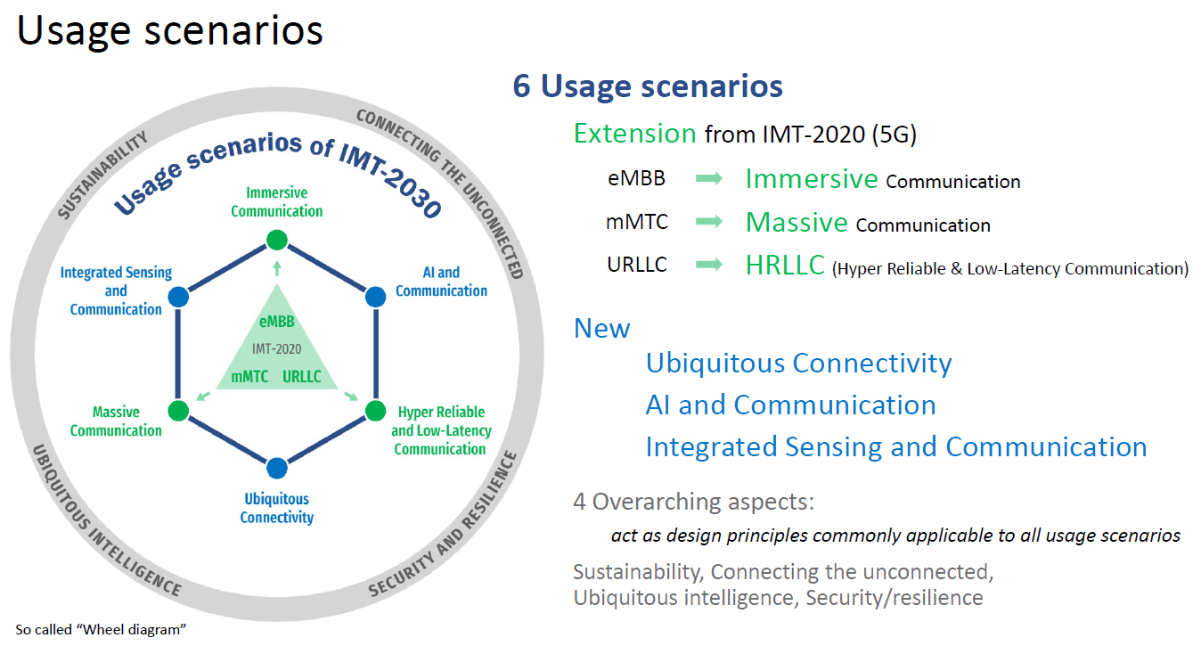
<p>Fast forward to 2023, ITU released the IMT-2030 framework (the <em>de facto</em> vision for 6G). The familiar triangle that describes 5G’s 3 use cases sits in the middle. But moving forward, they have evolved with ambitious targets. Immersive Communication (from eMBB) targets for peak data rates up to 1 Tbps, Hyper-Reliable Low Latency Communication (from URLLC) strives to achieve 0.1 ms latency with “seven-nines” reliability, and Massive Communication (from mMTC) caters to connection densities an order of magnitude higher.</p>

<figure style="margin: 1.8em 0 1.4em;">
  <img src="/images/imt2030-official.png" alt="ITU-R IMT-2030 framework diagram showing the six usage scenarios for 6G" style="max-width: 100%;" />
  <figcaption style="text-align: center; font-size: 0.82em; color: #7A6858; margin-top: 0.5em;">The six usage scenarios defined in the ITU-R IMT-2030 framework. Three evolve from 5G's service classes; three are additions that define what makes 6G genuinely new.</figcaption>
</figure>

<p>But the more interesting part of IMT-2030 is not the bigger numbers or more ambitious targets; rather, it is how three additional scenarios have been identified that have no counterpart in 5G, further “expanding” the triangle into a hexagon. They are, namely,</p>

<p><strong>Integrated Sensing and Communication (ISAC)</strong>: the network no longer just carry data; rather, it can also use the same hardware and its own radio signals to sense the physical environment, detecting objects and estimating device locations. The antenna that used to only convey information is now also a radar.</p>

<p><strong>AI and Communication</strong>: rather than running AI on top of the network as an afterthought, intelligence ought to be designed into the network architecture itself; for example, they can be used to revolutionize the way we do channel estimation, resource allocation, beam management, and network resource optimization. The network becomes an intelligent and proactive agent, not just a passive pipe.</p>

<p><strong>Ubiquitous Connectivity</strong>: seamless integration of terrestrial cells with satellites and aerial platforms, so that coverage is no longer bounded by where a cell tower was economical to build. We can thus reach deep rural areas, and serve maritime and aviation industries, thereby realizing the goal of “connecting the unconnected”.</p>

<p>Taken together, the vision for 6G is a shift from a communication network to a platform for communication, sensing, and computation—one that increasingly serves machines, infrastructure, and industrial systems as much as people holding phones.</p>

<h2 id="the-bottom-line">The bottom line</h2>

<p>If your 4G works fine for streaming and browsing, that will probably continue to be the case. What 5G and 6G are trying to solve is the set of problems that comes next: connecting the physical world at scale, enabling latency-sensitive control over wireless links, and building a network infrastructure that industry can rely on.</p>

<p>All in all, “faster internet” can mean more than just faster download speeds. The more precise framing is: <em>higher rates for different kinds of traffic, with different reliability and latency requirements, for many more types of users than just humans with smartphones.</em> That distinction is also what drives some of the exciting research and development works in the space of 5G, 6G and beyond.</p>

<hr />

<p><em>Next in the series: we will spend some time to discuss more on the three new scenarios set forth in IMT-2030/6G, and what they might actually involve technically, together with where the active research efforts are.</em></p>]]></content><author><name>Gary Lee</name><email>gary_lee@a-star.edu.sg</email></author><category term="5G" /><category term="5G" /><category term="6G" /><category term="eMBB" /><category term="URLLC" /><category term="mMTC" /><summary type="html"><![CDATA[Most people think 5G means faster downloads. It does---but is that all? The deeper story is about what 'faster' even means, and why three different answers lead to three different engineering problems.]]></summary></entry></feed>